GAZAR control valves are available in a variety of sizes (NPS ½ thru 24) and provide users with performance and flexibility. They can help solve an array of application needs from big to small, hot to cold, general to severe. GAZAR globe control valves have a selection of valve cages or plugs that can be interchanged to modify the inherent flow characteristic to linear, equal percentage, or quick opening to meet capacity demands.
GAZAR Rotary Control Valves
Rotary control valves generally have much higher maximum capacity than globe valves for a given body size. This fact makes rotary control valves attractive in applications where the pressure drop is rather small. Rotary control valves include ball, high-performance butterfly (used in throttling applications requiring large flow capacities (from NPS 2 to 72)).
Pneumatically-operated control valve actuators are the most popular type in use, but electric, hydraulic, and manual actuators are also widely used. The spring-and-diaphragm pneumatic actuator is most commonly specified due to its dependability and simplicity of design. Pneumatically-operated piston actuators provide high stem force output for demanding service conditions. Adaptations of both spring-and-diaphragm and pneumatic piston actuators are available for direct installation on rotary control valves.
Diaphragm Actuators
Pneumatically-operated diaphragm actuators use air supply from controllers, positioners, or other sources, including various style such as:
1. Direct-acting, in which the increasing air pressure pushes the diaphragm down and extends the actuator stem.
2. Reverse-acting, in which the increasing air pressure pushes the diaphragm up and retracts the actuator stem.
3. Reversible, in which actuators can be assembled for either direct or reverse action.
4. Direct-acting unit for rotary valves, in which the increasing air pressure pushes down on the diaphragm, which, depending on orientation of the actuator lever on the valve shaft, may either open or close the valve.
Piston Actuators
Piston actuators are pneumatically operated using high-pressure plant air up to 150 psig (10.3 bar), often eliminating the need for a supply pressure regulator. Various accessories can be incorporated to position a double acting piston in the event of supply pressure failure, including pneumatic trip valves and lock-up systems.
Manual Actuators
Manual actuators are useful where automatic control is not required, but where ease of operation and good manual control is still necessary. They are often used to actuate the bypass valve in a three-valve bypass loop around control valves for manual control of the process during maintenance or shut down of the automatic system.
Electric Actuators
Electric actuator designs use an electric motor and some form of gear reduction to move the valve plug. While electric actuators have traditionally been limited to on/off operation, some are now capable of continuous control. The use of brushless motors in electric actuators can reduce or eliminate motor burnout associated with turning the motor on and off rapidly. The initial purchase price still tends to remain above that of pneumatic actuation.
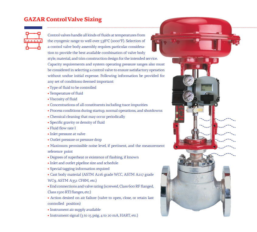
GAZAR Control Valve Sizing
Control valves handle all kinds of fluids at temperatures from the cryogenic range to well over 538°C (1000°F). Selection of a control valve body assembly requires particular consideration to provide the best available combination of valve body style, material, and trim construction design for the intended service.
Capacity requirements and system operating pressure ranges also must be considered in selecting a control valve to ensure satisfactory operation without undue initial expense. Following information be provided for any set of conditions deemed important:
- Type of fluid to be controlled
- Temperature of fluid
- Viscosity of fluid
- Concentrations of all constituents including trace impurities
- Process conditions during startup, normal operations, and shutdowns
- Chemical cleaning that may occur periodically
- Specific gravity or density of fluid
- Fluid flow rate I
- Inlet pressure at valve
- Outlet pressure or pressure drop
- Maximum permissible noise level, if pertinent, and the measurement reference point
- Degrees of superheat or existence of flashing, if known
- Inlet and outlet pipeline size and schedule
- Special tagging information required
Leave a Reply